In the early days, LED displays were primarily used in outdoor applications with larger pixel pitches. Since these displays were designed as static scan drivers, there was no significant space demand for driver ICs. However, as LED displays began to be used indoors, smaller pixel-pitch modules (i.e., higher resolution within the same physical size, achieved by denser LED placement) were introduced, leaving less space available for electronic components. To address this limitation, the dynamic scan driving method based on time-division multiplexing (TDM) was developed, also known as the line-scanning drive. In line-scanning drive mode, LED displays are typically categorized into two types: common cathode and common anode configurations.
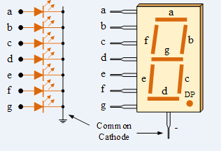
Operation of the Common Cathode Configuration
The common cathode configuration is widely used in LED displays and other semiconductor devices. Multiple LED cathodes (negative terminals) are connected to a shared ground, simplifying the circuit layout. Each LED anode (positive terminal) is connected to a separate control line. To light up an LED, a positive voltage is applied to its anode, allowing current to flow from the anode to the cathode, thus turning the LED on. This configuration is effective for controlling LEDs with a common ground reference and is ideal for applications such as seven-segment displays and RGB LEDs, where individual LED control is required.
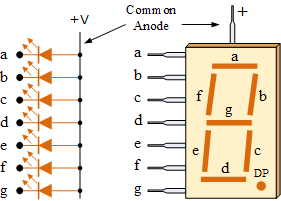
Operation of the Common Anode Configuration
The common anode configuration is also commonly used in LED displays and semiconductor devices. Multiple LED anodes (positive terminals) are connected to a shared positive voltage source, while each LED cathode (negative terminal) is connected to a separate control line.
To light up an LED, a lower (negative) voltage is applied to its cathode, enabling current to flow from the common anode through the LED to the cathode. This arrangement is well-suited for circuits that use a shared positive supply and allows individual LED control. The common anode configuration offers several advantages, which is why it is widely preferred in many electronic applications. These include compatibility with positive logic systems, simplified power supply design, and greater flexibility in circuit design.
Feature Common Cathode Common Anode
Connection All cathodes connected to a common ground All anodes connected to a common positive voltage
Control Method Individual anodes controlled with positive voltage Individual cathodes controlled with negative voltage
Compatibility Easier with ground-referenced control circuits Easier with positive logic control systems
Power Supply Design May be more efficient due to reduced voltage drops Simplifies design in systems with common positive voltage
Typical Applications Seven-segment displays, RGB LEDs Seven-segment displays, RGB LEDs
Driving Logic Positive voltage turns on the LEDs Negative voltage turns on the LEDs
Common Use Cases Digital clocks, calculators, multi-segment displays Digital clocks, calculators, multi-segment displays
Technical Differences Between Common Anode and Common Cathode
- Current Flow:
- Common Anode: Current flows from the PCB through the LED diode; RGB LEDs are powered by the same supply voltage and receive the same drive power, resulting in a higher forward voltage drop.
- Common Cathode: Current flows through each LED diode first, with the R, G, and B channels receiving current separately before returning to the IC’s negative terminal. This reduces forward voltage drop and internal conduction resistance.
- Power Supply:
- Common Anode: A uniform supply voltage (typically above 3.8 V, e.g., 5 V) is applied to all RGB LEDs, leading to higher power consumption.
- Common Cathode: Separate supply voltages are provided to the R, G, and B LEDs (e.g., 2.8 V for red, 3.8 V for green and blue), tailored to their actual requirements. This results in higher energy efficiency and reduced heat generation.
Both common cathode and common anode configurations are widely used in seven-segment displays, RGB LEDs, and other multi-segment displays. The choice depends on circuit design considerations:
- Common Cathode is typically preferred for ground-referenced logic.
- Common Anode is typically preferred for positive logic systems.
Source: Premteco + Tomo (Photo: Haikoto)